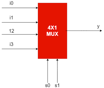
EXPLANATION:
A
multiplexer or in short mux is a combinational logic circuit used to pass only one
of the multiple inputs(i0,i1,i2,i3) at a time with the help of select lines(s0,s1)
to generate the output(y).
A 4x1(Four cross one) mux has four
inputs and 1 output. The output of a mux will always be one. The general
formulae for all types of multiplexers is, For 2n inputs,
the number of selects line will be n.
For 4x1 mux when s=00, the input line i0 will be transferred to the output y; when s=01, the input line i1 will be transferred to the output y; when s=10, the input line i2 will be transferred to the output y; when s=11, the input line i3 will be transferred to the output y.
Verilog code:
module mux4_1(input i0,i1,i2,i3,s1,s0,output y);
assign y=(s1==0)? ((s0==0)? i0:i1): ((s0==0)? i2:i3);
endmodule
Test Bench:
`timescale 1ns/1ns
module tb;
reg s0,s1,i0,i1,i2,i3;
wire y;
mux4_1 DUT(i0,i1,i2,i3,s1,s0,y);
initial
begin
s0=1'b0;s1=1'b0;i0=1'b0;i1=1'b0;i2=1'b0;i3=1'b0;
#15 s0=1'b0;s1=1'b0;i0=1'b0;i1=1'b0;i2=1'b0;i3=1'b1;
#15 s0=1'b1;s1=1'b0;i0=1'b0;i1=1'b0;i2=1'b1;i3=1'b0;
#15 s0=1'b0;s1=1'b0;i0=1'b0;i1=1'b0;i2=1'b1;i3=1'b1;
#15 s0=1'b1;s1=1'b1;i0=1'b0;i1=1'b1;i2=1'b0;i3=1'b0;
#15 s0=1'b0;s1=1'b0;i0=1'b0;i1=1'b1;i2=1'b0;i3=1'b1;
#15 s0=1'b0;s1=1'b0;i0=1'b0;i1=1'b1;i2=1'b1;i3=1'b0;
#15 s0=1'b1;s1=1'b1;i0=1'b1;i1=1'b0;i2=1'b0;i3=1'b0;
#15 s0=1'b0;s1=1'b0;i0=1'b1;i1=1'b0;i2=1'b0;i3=1'b1;
#15 s0=1'b1;s1=1'b0;i0=1'b1;i1=1'b0;i2=1'b1;i3=1'b0;
#15 s0=1'b0;s1=1'b1;i0=1'b1;i1=1'b0;i2=1'b1;i3=1'b1;
#15 s0=1'b1;s1=1'b1;i0=1'b1;i1=1'b1;i2=1'b0;i3=1'b0;
#15 s0=1'b0;s1=1'b0;i0=1'b1;i1=1'b1;i2=1'b0;i3=1'b1;
#15 s0=1'b1;s1=1'b0;i0=1'b1;i1=1'b1;i2=1'b1;i3=1'b0;
#15 s0=1'b0;s1=1'b0;i0=1'b1;i1=1'b1;i2=1'b1;i3=1'b1;
end
endmodule
WAVEFORM:
Cheers to you all..


0 Comments
If you have any doubts , please let me know
Emoji